Spongy brake levers rarely indicate a simple air bubble; they signal systemic neglect across chemical, mechanical, and thermal domains.
- Chemical incompatibility between DOT fluid and mineral oil destroys seal integrity, allowing air ingress and fluid leaks.
- Piston stiction and caliper misalignment create mechanical drag that mimics hydraulic failure but requires mechanical, not fluid, intervention.
Recommendation: Before opening the bleed port, audit seal compatibility, piston mobility, and pad contamination to isolate the true failure point.
That sinking feeling when your brake lever pulls back to the grip is unmistakable. Most riders immediately diagnose air in the hydraulic line and reach for a bleed kit, assuming the solution is simply to purge the system. Yet experienced mechanics recognize this as a reflexive platitude that often masks deeper mechanical failures. While trapped air certainly reduces fluid incompressibility, modern sealed systems rarely ingest air unless compromised by degraded seals, contaminated pistons, or thermal fade from undersized rotors.
The industry default of “bleed first, ask questions later” ignores the ecosystem surrounding your caliper. Chemical incompatibility between fluid types can swell seals into a gummy mess, creating the exact leak paths that allow air entry. Similarly, a sticky piston—immobilized by road grit or lubricant overspray—creates lever travel that feels identical to aeration, yet no amount of bleeding will restore function. Even ergonomic factors, like lever reach mismatched to hand size, can create a spongy sensation through poor mechanical advantage rather than hydraulic failure.
This guide treats the bleed procedure not as a starting point, but as the final verification step in a comprehensive diagnostic workflow. We will examine the chemical warfare occurring inside your master cylinder, the mechanical freedom required of your pistons, the thermal demands placed on E-bike systems, and the precise alignments necessary for drag-free operation. Only when these foundations are verified does bleeding become the corrective action, not the diagnostic guess.
To navigate this systematic approach to restoring stopping power, the following sections dissect each potential failure mode—from fluid chemistry to frame geometry—providing a logical sequence for isolating the root cause of lever sponginess.
Table of Contents: Understanding Hydraulic Brake System Failure Beyond Air Bubbles
- Mineral Oil vs DOT Fluid: Why Mixing Them Destroys Seals
- How to Mobilize Pistons Without Leaking Fluid
- 180mm vs 203mm: Is the Upgrade Necessary for E-Bikes?
- The Risk of Spraying Lubricant Near Calipers
- Adjusting Lever Reach for Small Hands and Better Control
- Why Height Charts Are Often Wrong for Short Riders
- Brake Pads and Chains: Why E-Bikes Eat Them 2x Faster
- Caliper Alignment: Stopping that Annoying Rubbing Noise
Mineral Oil vs DOT Fluid: Why Mixing Them Destroys Seals
The foundation of hydraulic braking integrity rests on chemical compatibility. Brake systems are designed around specific elastomer seals—nitrile (NBR) for mineral oil, ethylene propylene (EPDM) for DOT fluid. These polymers are not interchangeable. When DOT fluid contacts a mineral oil system, the glycol ether compounds attack the nitrile seals, causing them to swell, soften, and lose elastic memory. This degradation creates micro-gaps at the piston interface, transforming a sealed system into an air-permeable liability.
Understanding the hygroscopic nature of DOT fluids is equally critical. Unlike mineral oil, which is hydrophobic and maintains a constant boiling point, DOT fluid testing standards confirm the fluid absorbs approximately 3.7% water by volume over two years in a sealed system. This moisture lowers the wet boiling point precipitously, creating vapor bubbles under heavy braking loads that feel identical to air contamination from a leak. Riders often blame installation error when the culprit is simply aged fluid chemistry.
The following comparison illustrates why manufacturer specifications are absolute, not suggestions.
| Property | Mineral Oil | DOT Fluid (3/4/5.1) |
|---|---|---|
| Base chemistry | Petroleum distillate | Polyethylene glycol |
| Seal type required | Nitrile (NBR) | EPDM rubber |
| Hygroscopic (absorbs water) | No (hydrophobic) | Yes (2–3% per year) |
| Shelf life once opened | Indefinite | ~12 months max |
| Corrosive to paint/carbon | No | Yes |
| Toxicity | Low | Moderate–High |
| Boiling point stability | Constant (no wet/dry distinction) | Decreases as moisture is absorbed |
| Major brands using it | Shimano, Magura, Campagnolo, TRP | SRAM, Hope, Hayes |
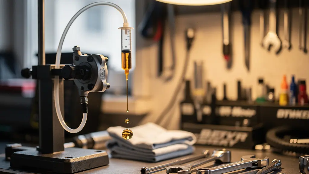
Cross-contamination does not require a full fluid swap to initiate catastrophic failure. Even residual mineral oil in a syringe used to top off a DOT system begins the chemical reaction. The visual evidence is stark: contaminated seals exhibit a glossy, bloated appearance distinct from the matte, crisp edges of healthy components.
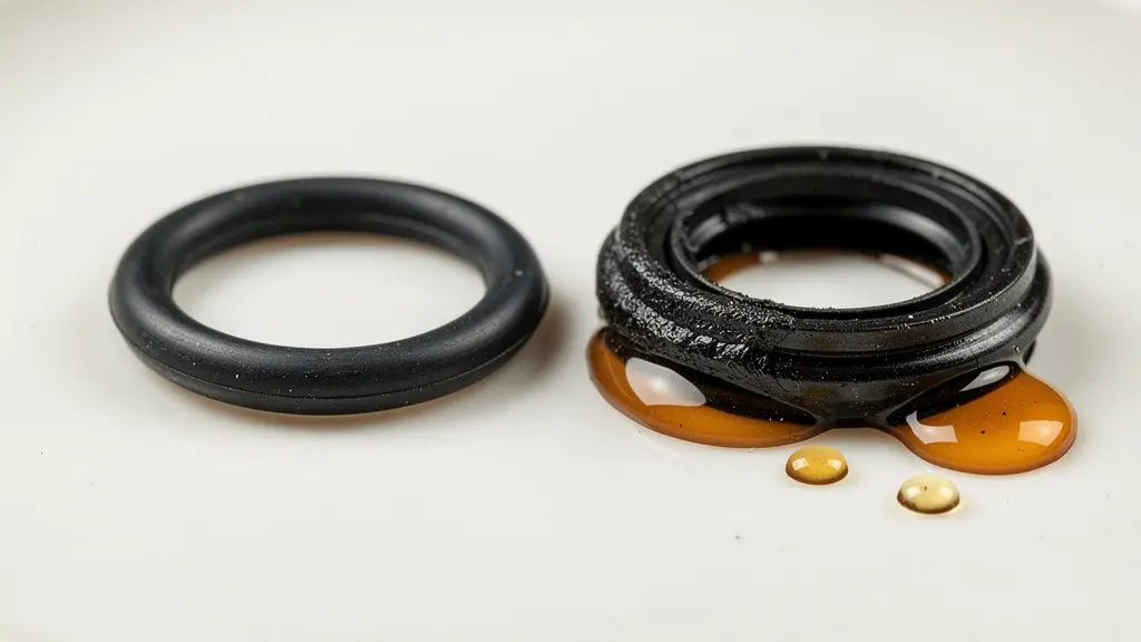
As shown above, the textural difference between compromised and functional seals is immediate. Once this swelling occurs, the seal can no longer retract the piston fully, causing drag and allowing air ingress during the piston’s return stroke. Verifying fluid compatibility must precede any bleed procedure.
Never assume two bottles labeled “brake fluid” are equivalent. The molecular interaction between seal and solvent determines whether your lever feels firm or fades into the grip.
How to Mobilize Pistons Without Leaking Fluid
Before condemning the hydraulic line as aerated, investigate piston stiction—the mechanical resistance that prevents caliper pistons from extending and retracting freely. A “lazy” piston that fails to advance creates asymmetric pad pressure, forcing the active piston to travel further before pad contact. This additional lever travel mimics the feel of air in the system, yet the fluid is fully incompressible.
The diagnostic protocol requires isolating mechanical function from hydraulic integrity. Remove the wheel and pads, then gently pump the lever to extend all pistons partially. Observe whether one piston advances while the other remains static. This imbalance indicates contamination or corrosion at the piston-seal interface, not air in the line.
Remediation involves controlled mobilization without introducing contaminants. The following procedure ensures pistons move freely without compromising seal integrity.
Action Plan for Restoring Piston Mobility
- Remove the wheel and brake pads from the caliper. Store pads face-up on a clean surface away from any fluids.
- Visually inspect all pistons by gently pumping the brake lever. Identify the ‘lazy’ piston — the one that moves less or not at all compared to the others.
- Using a flat plastic tire lever (never a metal screwdriver), gently push all pistons back into the caliper body evenly.
- Hold the freely-moving pistons in with the flat edge of the plastic tire lever, then gently pump the lever to extend only the stuck piston. Repeat 10–15 times.
- Clean each exposed piston surface with a lint-free cloth dampened with isopropyl alcohol. Never use chain lube, WD-40, or any oil-based product — this contaminates the system.
- Push all pistons back in, reinstall pads and wheel, and test for even pad contact by slowly squeezing the lever while observing the rotor gap.
This mechanical intervention often resolves sponginess that mechanics mistakenly attribute to aeration. A documented case from Teton Gravity Research illustrates this diagnostic error: a mechanic encountered brakes that felt spongy despite a fresh bleed. After verifying fluid quality, the investigation revealed stuck pistons causing uneven pad wear. The solution was cleaning and mobilization, not re-bleeding. The lesson is unequivocal: always verify piston mobility before assuming hydraulic failure.
Misdiagnosed Lazy Piston: When a Bleed Isn’t the Answer
A Teton Gravity Research mechanic documented the diagnostic workflow for brakes that felt spongy despite a fresh bleed. After checking fluid quality and pad wear, the real culprit was stuck pistons — one piston was not extending evenly, causing uneven pad wear and the sensation of reduced power. The fix was cleaning and mobilizing the pistons, not re-bleeding the system. The mechanic emphasizes always checking that pistons move freely and evenly as a critical step before any bleed procedure.
Regular mobilization prevents the crystallization of brake dust and corrosion that binds pistons. Treat this as preventative maintenance, not just a repair procedure.
180mm vs 203mm: Is the Upgrade Necessary for E-Bikes?
Thermal management defines brake performance on electric mountain bikes. Standard mountain bikes dissipate heat through rotor mass and surface area, but eMTB brake wear analysis confirms that typical e-mountain bikes carry 15–25 lbs (7–12 kg) of additional system weight compared to non-electric equivalents. This mass increases kinetic energy during descents, converting to thermal load that can overwhelm 180mm rotors.
When rotor temperature exceeds the boiling point of accumulated moisture in DOT fluid—or the vaporization point of mineral oil compounds—the result is brake fade. The lever pulls to the bar not because of air ingress, but because the fluid has vaporized internally. Upgrading rotor diameter increases thermal mass and surface area for heat dissipation, delaying this critical failure point.
The performance differential between rotor sizes is measurable and significant for heavy systems.
| Attribute | 180mm Rotor | 203mm Rotor |
|---|---|---|
| Braking torque (relative) | Baseline | ~13% higher leverage on caliper |
| Heat dissipation surface area | Lower | Significantly higher — more mass and surface to absorb and radiate heat |
| Brake fade on long descents | Higher risk for heavy e-bikes | Reduced risk — stays cooler longer |
| Weight penalty | Lighter (~20–40g less) | Slightly heavier, negligible on e-bikes |
| Best suited for | Lighter riders, XC, flat terrain, system weight under 100 kg | Heavier riders, aggressive trail/enduro, system weight over 100 kg (220 lbs) |
| Adapter required | Standard post-mount | +23mm post-mount adapter (e.g., from 180mm post) |
| Pad life impact | Standard | Longer — lower operating temperature reduces pad degradation |
For riders exceeding 100 kg total system weight or engaging in aggressive descending, the 203mm upgrade transitions from optional to essential. The larger diameter reduces operating temperatures, which extends pad life and maintains fluid viscosity.
The thermal demands of E-bike riding make rotor sizing a safety-critical decision. A spongy lever on a heavy E-bike often indicates thermal fade rather than air contamination, requiring mechanical upgrade rather than hydraulic service.
Select rotor diameter based on total system weight and descent frequency, not aesthetic preference.
The Risk of Spraying Lubricant Near Calipers
Aerosol lubrication represents one of the most common sources of systemic contamination in hydraulic disc brakes. The overspray from chain lubes, degreasers, or frame protectants travels further than visible evidence suggests, settling on rotors and porous pad materials. Once contaminated, the friction coefficient drops precipitously, requiring increased lever pressure that can be mistaken for air in the lines or worn pads.
The mechanism is insidious: petroleum-based aerosols bond with the phenolic resin in brake pads. During braking, the generated heat bakes these oils deeper into the compound, creating a glazed, glass-like surface that no longer generates friction effectively. The rider experiences a lever that pulls farther with less stopping power—a textbook spongy feel that sends them searching for bleed kits rather than replacement pads.
Prevention requires strict protocols during any maintenance involving lubricants. The following audit checklist isolates critical control points to prevent chemical contamination.
Essential Checklist for Preventing Brake Contamination During Maintenance
- Always remove wheels and store brake pads face-up away from the work area before performing any drivetrain lubrication or cleaning.
- Never spray lubricant directly onto components. Apply lube to a clean rag first, then wipe it onto the chain, pivot points, or stanchions.
- If you must use an aerosol spray, shield the caliper and rotor with a dedicated disc brake cover or a large, clean rag draped over them.
- After any drivetrain maintenance involving lubricants or degreasers, always wipe down rotors with isopropyl alcohol and a lint-free cloth as a final step.
- Handle brake pads only by their backing plate — finger oils on the friction surface can cause contamination and noise.
Real-world data confirms the severity of this issue. Ariel Rider’s technical documentation tracks numerous cases where riders contaminated pads during routine chain maintenance. Even minimal overspray settles on rotors and migrates into pad pores. Once heated, the damage is irreversible—cleaning cannot restore the friction compound, necessitating full replacement of pads and rotors.
Contaminated Pads After Chain Lubrication: The Hidden Cost of Overspray
Ariel Rider’s 2025 brake pad guide documents a common scenario where riders contaminate their brake pads during routine chain maintenance. Even a minute amount of overspray from aerosol chain lube settles on the rotor and porous pad material. When the rider then brakes, heat bakes the oil deep into the pad compound, making it nearly impossible to salvage. The guide notes that persistent squeal, glazing, or reduced stopping power after any lubrication work is almost always contamination, requiring full pad and rotor replacement rather than a simple cleaning.
Treat the caliper area as a sterile field during any lubrication task. The cost of prevention is negligible compared to the cost of component replacement.
Adjusting Lever Reach for Small Hands and Better Control
Hydraulic modulation depends on ergonomic leverage as much as fluid mechanics. When a rider cannot position their index finger optimally on the lever blade, they must engage additional fingers or compromise wrist angle. This reduced mechanical advantage creates the sensation that the lever “bottoms out” or feels mushy, often misdiagnosed as air in the system when it is actually poor ergonomic fit.
The goal is one-finger braking: using only the index finger while the remaining three maintain grip security. This technique requires precise adjustment of both lever reach (distance from bar to blade at rest) and bite point (where pad contact occurs in the lever stroke). Riders with smaller hands face particular challenges, as factory-default lever positions often assume average male hand dimensions.
Adjustments must be made iteratively, testing for both comfort and power modulation. Follow this sequence to optimize control without compromising safety.
Adjustment Protocol for One-Finger Braking Efficiency
- Locate the reach adjustment screw on your brake lever (usually a small hex screw on the lever body near the pivot). Turn it to bring the lever blade closer to the handlebar grip until you can comfortably wrap your index finger around the lever tip without stretching.
- Position the brake lever clamp on the handlebar so the lever blade is a natural, straight extension of your forearm when in your riding attack position. A slight downward angle (roughly 15–20 degrees below horizontal) is typical for mountain biking.
- If your brake has a free stroke or bite point adjustment screw (separate from reach), use it to set where the pads engage. Turn it so the pads contact the rotor after approximately 10–15mm of lever travel — this gives you immediate power without the lever feeling ‘dead’ at first pull.
- Test ride in a safe, flat area. You should be able to achieve full stopping power with just your index finger, with the lever never touching your other fingers or the grip. If the lever bottoms out against the bar, you may need a bleed rather than further reach adjustment.
Incorrect lever position contributes significantly to arm pump—forearm muscle fatigue caused by over-gripping and poor wrist alignment. A lever set too far from the bar forces the rider to over-extend, reducing modulation sensitivity and increasing perceived sponginess.
Optimize lever position before questioning fluid integrity. The human-machine interface is the first variable to eliminate from diagnostic consideration.
Why Height Charts Are Often Wrong for Short Riders
Frame sizing conventions rely on anthropometric averages that fail riders with non-standard proportions. A rider may fit a manufacturer’s height chart for a “medium” frame yet experience compromised brake control due to excessive cockpit reach. This is particularly acute for shorter riders with a negative ape index (arm span shorter than stature), who must overextend to reach the handlebars.
When reach is excessive, the rider’s fingers stretch to contact the lever, reducing the mechanical advantage available for modulation. The wrist extends beyond neutral, compromising strength and sensitivity. The rider reports a lever that feels “soft” or “wooden”—not because of hydraulic issues, but because they cannot generate sufficient leverage at the blade.
As The Lost Co Bike Shop emphasizes in their technical guidance:
Responsive brakes are absolutely the most confidence inspiring aspect of a dialed bike.
– The Lost Co Bike Shop, How To Bleed Shimano Mountain Bike Brakes
This responsiveness depends on fit. BikeRadar’s fitting analysis confirms that generic height charts assume average body proportions. The solution requires prioritizing cockpit reach measurements—handlebar distance, stem length, and lever position—over frame size charts. Treating the ability to comfortably reach and control brake levers as the primary fit criterion often necessitates smaller frame sizes or shorter stems than height-based recommendations suggest.
The Ape Index Problem: When a ‘Correct’ Frame Size Compromises Braking
BikeRadar’s fitting guidance highlights that generic manufacturer height charts assume average body proportions. A shorter rider with a negative ape index (arm span shorter than height) on a ‘correctly’ sized frame will still over-reach for the handlebars. This extended reach forces the rider’s fingers to stretch further for the brake levers, reducing braking leverage and modulation. The solution is to prioritize cockpit reach measurements — handlebar distance, stem length, and lever position — over frame size charts, treating the ability to comfortably reach and control the brake levers as the primary fit criterion.
Never accept compromised control due to arbitrary sizing charts. The frame must fit the rider’s specific anthropometry, not a statistical average.
Brake Pads and Chains: Why E-Bikes Eat Them 2x Faster
The increased mass and sustained speeds of E-bikes generate thermal and mechanical loads that accelerate consumable wear. E-bike brake pad data indicates a lifespan between 500 to 3,000 miles, with aggressive downhill riders consuming sets in under 500 miles. This consumption rate far exceeds that of conventional mountain bikes, creating maintenance intervals that inexperienced E-bike owners may miss.
Worn pads reduce the piston extension required to contact the rotor. As friction material thins, pistons must extend farther from the caliper body, effectively increasing the fluid volume required in the system. This creates lever travel that mimics air contamination or master cylinder failure. The system is hydraulically sound, but mechanically depleted.
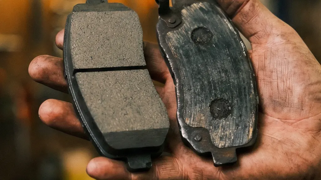
The visual difference between serviceable and depleted pads is stark, as shown above. Continuing to ride worn pads risks backing plate contact with the rotor, causing irreversible damage to the braking surface and potential contamination of the piston bore with metallic debris.
Community data from EMTB Forums confirms extreme variance in pad life based on riding style. One rider on a 22 kg Trek Rail reported 2,000–3,000 km per set, while an aggressive enduro rider on a 26 kg bike reported only 300–400 km. This 5–10x variation demonstrates that terrain and technique dramatically affect consumption rates.
E-Bike Pad Wear in Real-World Conditions: EMTB Forum Data
An EMTB Forums community survey compiled real-world data from e-mountain bike riders. A rider at 105 kg total system weight on a 22 kg Trek Rail with Shimano XT 4-piston brakes and metallic pads reported 2,000–3,000 km before replacement. In contrast, a rider with a 26 kg enduro e-bike doing aggressive bikepark and trail rides reported just 300–400 km per set of pads. These figures demonstrate that terrain and riding style can cause a 5–10x variation in pad lifespan on the same type of bike, confirming that e-bikes consume brake pads at dramatically accelerated rates compared to standard bikes.
Establish inspection intervals based on mileage and weight, not time. High-load E-bike usage demands proactive maintenance schedules.
Key Takeaways
- Spongy levers indicate systemic failure—verify chemical compatibility, piston mobility, and pad wear before bleeding.
- Mineral oil and DOT fluid are chemically incompatible; mixing them destroys seals and invites air ingress.
- Thermal management on E-bikes requires larger rotors (203mm) to prevent vaporization that mimics air contamination.
- Mechanical drag from misaligned calipers or stuck pistons creates lever travel unrelated to hydraulic integrity.
Caliper Alignment: Stopping that Annoying Rubbing Noise
Mechanical drag from misaligned calipers creates persistent friction that generates heat and accelerates pad wear. This drag forces the rider to apply more lever pressure to overcome initial resistance, creating the impression of a soft or unresponsive system. The “shing-shing” sound of a rubbing rotor indicates that the caliper body is not parallel to the rotor plane, causing one pad to contact the braking surface continuously.
Traditional “squeeze-and-tighten” alignment methods often fail because they rely on the pistons self-centering. If pistons are not extending evenly—a condition addressed in previous sections—the caliper centers on an offset axis, perpetuating drag. A visual alignment method provides superior results by eliminating piston bias from the equation.
The following procedure ensures mechanical neutrality before hydraulic pressure is applied.
Visual Calibration Method for Drag-Free Alignment
- Loosen both caliper mounting bolts just enough that the caliper can slide freely on the post mount. Do not remove the bolts entirely.
- Instead of squeezing the lever (which can center off-axis if pistons are uneven), use a flashlight or white piece of paper behind the rotor to visually check the gap between the rotor and each pad.
- By hand, nudge the caliper body left or right until you see equal, even daylight on both sides of the rotor through the pad slot.
- While holding the caliper in position with one hand, tighten the mounting bolts in an alternating pattern (one bolt a quarter turn, then the other) to prevent the caliper from shifting as you tighten.
- Spin the wheel and listen. If you still hear a faint rub, repeat with finer adjustments. If you hear a rhythmic ‘ting’ once per rotation rather than constant rubbing, the rotor is slightly warped — that requires truing, not caliper realignment.
Distinguishing between caliper misalignment and rotor warpage is essential. A constant “shing” indicates caliper offset, correctable through realignment. A single “ting” at one point in the rotation indicates rotor truing needs. International Standard (IS) mounts require particular attention, as adapter plates introduce additional failure points for misalignment compared to direct Post Mount systems.
Eliminate mechanical drag to isolate true hydraulic issues. A caliper that drags cannot be properly diagnosed for aeration until it moves freely.
Frequently Asked Questions on Hydraulic Brake Systems
What is one-finger braking and why does it matter?
One-finger braking means using only your index finger on the brake lever while the remaining three fingers grip the handlebar securely. This is the gold standard for modern mountain biking because it maximizes both braking modulation and steering control simultaneously, especially in technical terrain.
What is the difference between lever reach and bite point adjustment?
Lever reach controls the physical distance between the lever blade and the handlebar grip at rest — how far your finger has to stretch to touch it. Bite point (or free stroke) controls where the brake pads actually engage the rotor during the lever pull. Both should be adjusted independently for optimal feel.
Can incorrect lever position cause arm pump?
Yes. If the lever is too far from the bar, the rider must over-extend their fingers or compromise their wrist angle, leading to forearm muscle fatigue (arm pump) on long descents. Proper lever position keeps the wrist neutral and reduces grip strain significantly.
What does a constant ‘shing-shing’ noise when spinning the wheel indicate?
A constant, rhythmic rubbing sound that occurs with every wheel rotation typically indicates a misaligned caliper. The caliper body is slightly off-center relative to the rotor, causing one pad to lightly drag. This is fixed by loosening the caliper bolts and realigning.
What causes a sharp ‘ting’ or ‘ping’ once per wheel rotation?
A single, distinct metallic sound at one specific point in the wheel’s rotation indicates a slightly warped rotor. The rotor has a small bend that contacts the pad at one spot. This requires rotor truing with a dedicated rotor truing tool or an adjustable wrench, not caliper realignment.
What is the difference between Post Mount and IS Mount for calipers?
Post Mount (PM) has two threaded holes directly in the frame or fork, allowing the caliper to slide laterally for easy alignment. International Standard (IS) uses a separate adapter plate bolted to the frame, which then accepts the caliper. IS mounts require more precise shimming and can be a hidden source of chronic misalignment if the adapter is not perfectly installed.