
In Summary:
- Galvanic corrosion between aluminum stems and stainless steel bolts can accelerate material degradation by sixfold compared to compatible assemblies
- Tire sidewalls suffer UV and ozone aging that reduces rubber damping capacity by up to 14% before visible cracking appears
- Disc brake pads require replacement when friction material drops below 1mm; relying on lever feel indicates critical safety margin has already been compromised
- Hub motor wheels demand monthly spoke tension verification due to torque-induced stress concentrations unique to electric drivetrains
- NTA 8776 certified helmets provide extended temporal and parietal coverage designed for kinetic energy thresholds exceeding standard bicycle certifications
Most riders perform safety checks only when a component feels wrong. By that point, material fatigue has already progressed to catastrophic failure thresholds. The difference between a safe commute and a sudden mechanical failure often lies not in the quality of your components, but in the microscopic accumulation of wear that precedes visible damage.
Conventional wisdom suggests “checking brakes and tires” without explaining the chemical and physical processes—galvanic corrosion, elastomer oxidation, spoke tension redistribution—that actually compromise safety. This gap between generic advice and engineering reality leaves riders vulnerable to failure modes they cannot see until it is too late.
The M-Check is not merely a list of visual inspections; it is a systematic protocol for intercepting cascading failures before they reach critical kinetic energy. By understanding why components fail—the electrochemical reactions at bolt interfaces, the shear forces acting on hub motor spokes, the vibration transmission destroying optical stabilization—you transform routine maintenance into predictive safety engineering.
This guide examines eight critical failure points through the lens of material science and mechanical stress, providing a methodical framework that takes two minutes but prevents months of recovery.
For those who prefer visual learning, the following video demonstrates the complete M-Check procedure in a condensed format, complementing the technical analysis below with practical demonstrations of each safety checkpoint.
The following sections break down each checkpoint in the M-Check sequence, moving from the cockpit through the drivetrain to security and protection systems. Each segment explains the underlying failure mechanics and provides specific measurement criteria to eliminate subjective guesswork from your pre-ride routine.
Table of Contents: Complete Mechanical Safety Assessment
- Why Stem Bolts Loosen Over Time (And the Danger It Poses)
- Looking for Cuts and Glass: Preventing Blowouts at Speed
- Resin vs Sintered Pads: Checking Wear Limits Visually
- The Risk of Loose Spokes on Hub Motor Wheels
- Grips and Pedals: Checking for Play and Security
- How to Lock Your Frame and Wheels to Prevent Component Theft
- The Risk of Destroying Your Phone Camera on Handlebar Mounts
- NTA 8776 Helmets: Why Standard Bike Helmets Aren’t Enough for E-Bikes
Why Stem Bolts Loosen Over Time (And the Danger It Poses)
The interface between your stem and steerer tube represents a critical failure point where electrochemical corrosion meets mechanical stress. Most modern stems utilize aluminum bodies clamped by stainless steel bolts—a pairing that creates galvanic potential. A 2024 SINTEF study on aluminum–stainless steel bolted connections reports total weight loss approximately six times higher than aluminum–aluminum assemblies under identical environmental conditions, indicating accelerated material degradation at the clamp interface.
This microscopic material loss occurs beneath the bolt head and within the stem clamp bore, invisible to casual inspection. As corrosion products accumulate, the effective clamping force diminishes despite the bolt remaining visually tight. The danger manifests not as gradual wobble but as sudden catastrophic separation, typically under maximum loading scenarios such as emergency braking or pothole impacts.
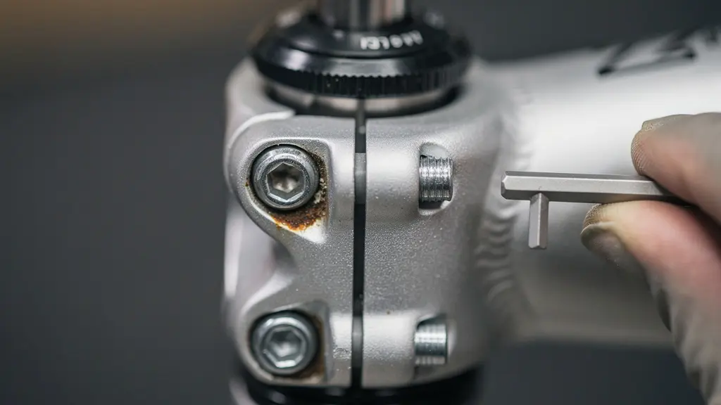
As ENVE Support Center emphasizes regarding fork installations: “Torque the stem steerer clamp bolts as specified by the stem manufacturer (do not exceed 6Nm).” This specification exists not merely to prevent crushing carbon fiber but to maintain consistent preload against vibration-induced loosening. Exceeding torque ratings strips threads or crushes clamping surfaces, while insufficient torque allows the micro-movements that accelerate galvanic corrosion.
Inspect stem bolts monthly using a calibrated torque wrench, looking specifically for white aluminum oxide residue around bolt heads—a telltale indicator that galvanic corrosion has compromised the interface.
Looking for Cuts and Glass: Preventing Blowouts at Speed
Tire integrity assessment extends far beyond tread depth inspection. The sidewall compound faces continuous degradation from ultraviolet radiation and atmospheric ozone, environmental factors that initiate elastomer chain scission long before visible cracking appears. A 2025 open-access materials study on UV and ozone aging reports effective damping temperature ranges decreased by 3.4–14% after accelerated aging in carbon black-filled rubber materials, indicating structural compromise before cosmetic failure.
This degradation creates a false sense of security. A tire may hold pressure adequately in static conditions yet suffer catastrophic blowout under dynamic loading when centrifugal forces and thermal expansion stress the compromised sidewall matrix. Glass fragments embedded in tread blocks act as stress concentrators, creating initiation points for rip propagation that travels at velocities exceeding the rubber’s tear resistance.
A practical analysis of MTB tire sidewall cracking frames this deterioration as a safety signal rather than cosmetic issue, linking premature failure to UV exposure, pressure errors, and harsh chemical cleaners. When cracks deepen beyond superficial surface glazing, the casing threads become exposed to moisture and continued flexural stress, creating a cascade failure mode where a single impact separates the tread from the casing.
Rotate wheels slowly while applying tactile pressure to the sidewalls, feeling for sharp inclusions or cord deformation. Check for flat spots or scalloped wear patterns that indicate casing damage beneath the rubber. Any tire exhibiting exposed threads, bulges, or cuts deeper than 1mm requires immediate replacement regardless of remaining tread depth.
Resin vs Sintered Pads: Checking Wear Limits Visually
Brake pad assessment demands direct visual inspection of the caliper cavity rather than reliance on lever feedback. A 2024 brake maintenance explainer summarizes typical pad replacement thresholds as approximately 1mm of remaining friction material, with an absolute minimum of 0.5mm, explicitly excluding the steel backing plate from measurement. Resin (organic) pads typically display faster wear but provide quieter operation, while sintered (metallic) compounds endure higher thermal loads but wear rotors more aggressively.
Visual identification between types becomes critical when assessing wear patterns. Resin pads exhibit uniform thickness reduction with smooth, glossy heat-glazed surfaces when overheated. Sintered pads show metallic sparkle within the composite and may develop thermal cracking or backing plate warping under sustained downhill loads. Both types share a common failure mode: backing plate contact with the rotor, which causes immediate scoring and catastrophic loss of braking efficiency.
Your 5-Step Disc Brake Safety Verification Protocol
- Look directly into the caliper to assess pad friction material (do not judge by lever feel alone on hydraulics)
- If you can see the brake piston protruding, stop and inspect pad material immediately—pads may be worn beyond safe limits
- Confirm you are measuring friction material only (exclude the backing plate)
- Spin the wheel and watch rotor-to-pad alignment; investigate rubbing, chirping, or visible rotor wobble before riding
- Visually check the rotor for heat discoloration and obvious scoring, which can indicate overheating or backing-plate contact
As CyclingSavvy notes in their disc brake maintenance guidelines: “With hydraulic disc brakes, if the brake lever has moved closer to the handlebar, it is usually too late.” This warning highlights the lag between pad wear and system feedback; hydraulic systems compensate for pad thinning through increased piston extension until mechanical limits are reached, providing no tactile warning during the critical degradation phase.
The Risk of Loose Spokes on Hub Motor Wheels
Electric bicycle hub motors introduce unique structural loading patterns that differ fundamentally from traditional wheel designs. The concentrated mass of the motor increases unsprung weight while transmitting drive torque directly through the spoke flanges rather than through the freewheel mechanism. This configuration creates alternating tension cycles during acceleration and regenerative braking that exceed the fatigue thresholds of conventional spoke arrangements.
A 2024 open-access Scientific Reports paper analyzes compliant spoke deformation as a structural mechanism for stiffness control, offering critical insight into how altered spoke tension redistributes loads across the wheel architecture. When one spoke loosens, its share of radial and torsional loads transfers immediately to adjacent spokes, creating a cascading failure pattern where progressive tension loss accelerates exponentially.
The consequences extend beyond simple wheel trueness issues. A loose spoke can wind up during torque application, then release suddenly, creating a shuddering feedback through the handlebars that mimics brake chatter or bearing failure. In severe cases, multiple simultaneous spoke failures allow the rim to contact the motor casing, locking the wheel instantaneously.
Treat any loose spoke as a safety issue requiring immediate cessation of riding. Check spoke tension monthly by plucking each spoke and listening for consistent pitch, or use a tension meter for quantitative assessment. Because rear hub motors increase spoke stress compared with non-motor wheels, professional truing should occur every 500 miles or following any impact event.
Grips and Pedals: Checking for Play and Security
Contact point security represents the interface between rider input and machine response, making microscopic play in grips or pedals disproportionately dangerous. Handlebar grips that rotate under torsional load—or slide longitudinally during impact—compromise emergency maneuver precision. The rubber-to-metal interface degrades through sweat chemistry, UV exposure, and mechanical abrasion, creating a condition where grips appear visually secure yet offer compromised friction coefficients when wet.
Test grip security by attempting to rotate the grip against the bar with maximum hand torque while stationary. Any movement indicates either worn grip material or insufficient clamping force from integrated locking rings. For slip-on grips without collars, the friction fit relies entirely on rubber elasticity; aging compounds lose their compression set, creating a delayed failure mode where grips slide inward during impacts, narrowing hand position and compromising control leverage.
Pedal play indicates bearing degradation, spindle wear, or crank arm damage. Grasp the pedal body and attempt lateral movement relative to the crank arm. Any perceptible motion—typically manifesting as a “click” felt through the sole—indicates that the bearing preload has been lost. This play creates impact loading during the power stroke that can rapidly ovalize crank threads or fracture pedal spindles without warning.
Inspect grip clamps for corrosion and verify that set screws remain seated with threadlocker compound intact. For pedals, check that the axle does not rock within the crank threads and that the pedal body rotates smoothly without notchiness or lateral slop.
How to Lock Your Frame and Wheels to Prevent Component Theft
Security constitutes an integral component of safety; a stolen bicycle strands the rider, while component theft—a seat, wheel, or handlebar—creates a hazardous situation when discovered mid-ride. Bike Index theft survey findings summarized in 2025 show that 59% of stolen bicycles were locked at the time of theft, with 35% secured by cable locks and 26% by U-locks, indicating that locking methodology proves as critical as the locking device itself.
Cable locks offer minimal resistance to portable cutting tools, functioning primarily as visual deterrents. U-locks provide superior shear resistance but often secure only the frame, leaving quick-release wheels vulnerable. The optimal strategy employs the “Sheldon Brown” method: position the U-lock through the rear wheel inside the rear triangle, capturing both the wheel and frame to the immovable object, as the rear wheel is typically more valuable and harder to replace than the front.
A synthesis of FBI 2023 bicycle theft data illustrates geographic risk variations, with certain states showing disproportionately high recovery rates when specific locking protocols are followed. Documentation proves equally critical; photograph your locked configuration with the serial number visible, creating timestamped evidence for law enforcement and insurance claims.
Before riding, physically confirm that quick-release levers are closed with sufficient cam pressure to leave an imprint on the palm, or that thru-axles are fully seated and torqued. Perform a quick upward tug on the saddle to verify seatpost clamp integrity, as saddle theft often damages the clamp mechanism, creating a hidden failure point.
The Risk of Destroying Your Phone Camera on Handlebar Mounts
Handlebar-mounted smartphones present a hidden cost to riders relying on navigation apps. Modern cameras utilize optical image stabilization (OIS) systems comprising microscopic gyroscopic sensors and voice coil motors that compensate for hand tremors. Apple Support documentation confirms that “long-term direct exposure to high-amplitude vibrations within certain frequency ranges might degrade the performance of these systems,” specifically warning that motorcycle and high-power bicycle engines generate damaging harmonic frequencies.
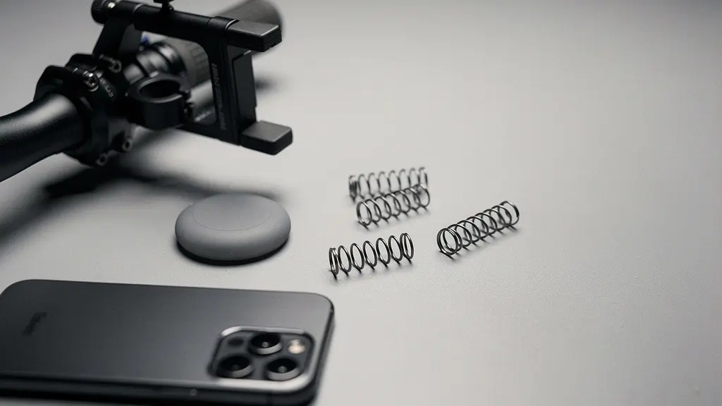
Bicycle handlebars transmit significant vibration despite appearing stable. A 2024 open-access Sensors paper compares vibration response in steel and carbon-fiber bicycle handlebars, demonstrating that material composition significantly alters vibration transmission characteristics. Rigid aluminum cockpits transmit high-frequency road buzz directly to mounted devices, while carbon fiber dampens certain frequencies but may resonate at amplitudes that coincide with OIS actuator natural frequencies.
The damage manifests gradually: blurry photos, jittery video, or complete autofocus failure. By the time symptoms appear, the delicate suspension mechanisms within the camera module have suffered permanent mechanical wear. This represents a significant financial risk when the phone serves as the primary navigation and emergency communication device.
If navigation is essential, utilize dedicated GPS units designed for vibration resistance, or employ viscoelastic damping mounts specifically engineered to isolate the frequency ranges that damage OIS systems. Alternatively, pocket the phone and use audio cues for turn-by-turn directions, eliminating both the theft risk and the vibration damage vector.
Key Takeaways
- Material incompatibility (aluminum/stainless interfaces) creates galvanic corrosion that compromises structural integrity before visual indicators appear
- Brake pad wear limits must be verified visually at the caliper, as hydraulic systems mask depletion until critical safety margins are exhausted
- Hub motor wheels require specific spoke tension monitoring due to torque transmission patterns that differ from conventional drivetrains
- NTA 8776 certification indicates helmet protection designed for kinetic energy thresholds exceeding standard bicycle impact scenarios
NTA 8776 Helmets: Why Standard Bike Helmets Aren’t Enough for E-Bikes
Standard bicycle helmets—certified to CPSC or EN 1078 standards—assume impact velocities and energy thresholds consistent with human-powered cycling. Electric bicycles capable of sustained speeds exceeding 25 km/h generate kinetic energy that exceeds the protection parameters of these traditional certifications. The NTA 8776 standard specifically addresses this differential through enhanced coverage and impact absorption requirements.
| Feature | NTA 8776 | CPSC | EN 1078 |
|---|---|---|---|
| Intended use case | E-bike / speed-pedelec-oriented protection emphasis | Standard bicycle helmet certification (US) | Standard bicycle helmet certification (EU) |
| Coverage emphasis | Extended coverage (side/rear) compared to typical bicycle standards | Standard coverage | Standard coverage |
| Testing emphasis (high-level) | Higher-energy e-vehicle context than traditional bicycle-only assumptions | Traditional bicycle impact context | Traditional bicycle impact context |
As illustrated in a comprehensive Cyclingnews guide reviewing e-bike helmets, NTA 8776 certification indicates extended temporal and parietal coverage designed to protect against the specific impact angles and velocities associated with e-bike accidents. The standard requires greater impact absorption at the sides and rear of the head—areas typically underprotected in racing-oriented designs that prioritize ventilation and weight reduction over coverage.

The physical differences are measurable: NTA 8776 helmets typically extend lower on the occipital bone and include more substantial temple protection. When combined with technologies like MIPS (Multi-Directional Impact Protection System), these helmets address the rotational forces common in high-speed slides on asphalt surfaces.
For riders transitioning from conventional bicycles to e-bikes, retaining a standard helmet creates a false equivalence of protection. The kinetic energy at 32 km/h exceeds that at 25 km/h by 64%, demanding commensurate protection that only speed-pedelec certified helmets provide.
Implement the M-Check as a non-negotiable pre-ride protocol, treating each component inspection as a critical data point in your personal risk assessment matrix.